
The electroplating laboratory technician may be asked to grow a metal object from scratch, rather than merely plate an existing part. The result, before final external machining, is called an electroform.
Electroforming involves much more than merely plating a long time. Critical issues need to be addressed to ensure success. While electroforming involves science, it is truly an art.
Definitions and Basics

Microwaves are electromagnetic waves with a wavelength in the range of 0.001–0.3 meters.
When creating a microwave feedhorn via electroforming, the scientist will grow it onto a mandrel. A mandrel is roughly comparable to a photographic negative. The desired end-result is not the negative, but the photo. Once the electroform is “developed”, the scientist removes the “negative”, which in this case is the mandrel.
Now that we’ve gotten the definitions and basics out of the way, let’s take a closer look at electroforming copper microwave feedhorns using aluminum mandrels.
Mandrel Basics
The mandrel of choice is often aluminum, because it’s easy to remove without damaging the end result. After the object (in this case, a microwave electronics feedhorn) is grown and any external machining has been performed, the aluminum is removed.
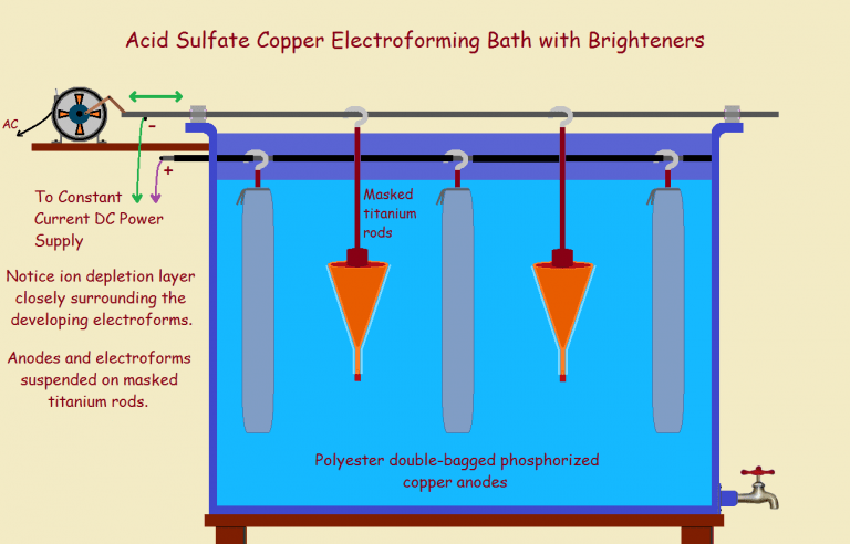
The most common metals electroforming onto a mandrel are copper and nickel. The copper bath, which we will discuss here, is acid sulfate copper bath. This bath consists of copper sulfate with added sulfuric acid. The ratio of sulfuric acid to copper sulfate may be 4-1/2 to 1 or greater. Bath providers offer guidelines.
A variety of aluminum alloys may be used to construct the mandrel. For strength, a copper-rich alloy such as 2024 is often the choice. However, if small openings are involved, the aluminum may be a zinc alloy such as 7075. This helps prevent clogging.
Mandrel Design and Construction
The electrical engineer designs his feedhorn. The drawing is then submitted to the machine shop. The machinist determines the alloy of aluminum to use. The horn is lathed (turned on a lathe) to a measurement tolerance of 0.0002″ (0.005 mm).
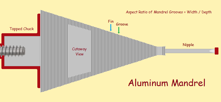
The front of the mandrel is called the nipple. It is machined longer than the finished length, since final machining will require that the lathe holds the unfinished electroform at both ends. The nipple has a center point tapped, or drilled, at its end for accuracy.
Normal guidelines dictate grooves have an aspect ratio (the ratio of width to depth) of 1:1, or, if that must be pushed, no more than 1:2 maximum. The author has grown feedhorns with a 1:5.7 aspect ratio! How he did this will be discussed below.
The mandrel chuck is carefully threaded so it can be screwed onto a strong, conductive titanium rod with a hook at the top. It is hung from the hook on the electrically negative cathode bar of the electroforming bath (The negative cathode draws the positive cation). Much of the rod is electrically isolated from the bath by means of shrink tubing sealed at ends with vinyl polymer coating, so it will not plate.
Cleaning and Preparation
After rinsing with solvent and drying (if necessary), a weak alkaline soak is used to remove the protective oxide layer aluminum forms immediately after machining. Within seconds, the horn is immersed in a sodium zincate solution, with initial swirling, for at least 30 seconds and perhaps as long as 10 minutes. This solution immersion plates a very thin coat of zinc (Zn) onto the aluminum (Al). The reaction scheme is:
Na2Zn(OH)4 + 2 Al → 2 NaAlO2 + Zn + 2H2O
The zincate coat is time-sensitive. Accordingly, the zincated mandrel is rinsed, then quickly immersed – electrically hot – into a copper cyanide flash bath. A flash bath is a bath is intended to quickly throw down (into the deepest recesses) a very thin coat of copper. It is the excess or free cyanide that enables this.
Next, since the end goal is to have the feedhorn coated with pure gold (rather than an alloy, since gold provides maximum electrical conductivity on the interior surface of the final horn), the copper flashed surface is plated in a gold flash bath, followed by a sulfite bright gold bath plating that coats the horn with hundreds of microinches to as much as one or two mils of gold (1 mil = 1000 microinches), depending on the need.
If it is deemed necessary, but only if it is deemed necessary, an additional nickel layer may be applied, next. If not, another brief cyanide copper flash is applied to assure adhesion between layers. Finally, the mandrel is ready for the electroforming bath.
A Few Tips, Then Bath Time!
The power supplies used are high-current, low voltage supplies, operated in constant current mode. This mode assures that, although the voltage may fluctuate, the current will not. Otherwise the bath will not function properly.
As to bath details… the anodes should be double-bagged (with polyester bags), and aeration should either not be used, or kept down to a minimum. This is because anodes produce microscopic particles that can reach the part to be plated, attach to it, and produce ruinous pitting. As time passes, the anodes shrink, and may detach themselves from their connective titanium rods. Check them regularly. Get a feel for their rough weight and attachment to the rod.
The mandrel is ready for the bath. There is no need to enter the electroform bath electrically hot. Now, referring to the image of the mandrel above, you will note the end horn is the nipple portion. The very tip is masked. It is the part just above that that receives the heaviest electrical jolt, as it were. What? In order to understand what actually happens, we need to introduce the concept of current density.
Cathode Current Density
Picture a cube. Imagine it is immersed into a liquid in an electrical field and the cube is part of the circuit. The only electrical connection is the liquid itself, which entirely surrounds all surfaces of the cube. How does current enter the cube?
Can you visualize it entering each side of the cube? Think of the electrons as very small bullets shot in such a way that the bullets are equally far apart on all sides. What would the edges look like? The corners?
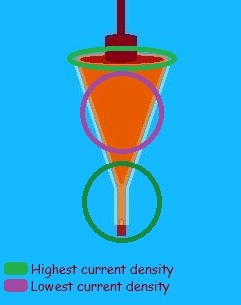
The edges would be more riddled because bullets from both sides of the edge would be penetrating the cube. And at the corners, bullets from three sides! The holes are denser at these locations. In fact, the current is denser at the locations. See the image. Why is this important? Because an electroplating bath is designed to function best within a moderately narrow range of current densities.

For instance, an acid sulfate copper bath may function best between 10 and 30 amperes-per-square-inch of surface area. If the bath is set at 30 amps per square foot, that may be fine for the center of the mandrel, but it would be too high for the nipple portion, and perhaps for the top edge as well. Too high a current density can produce dendrites – finger like protrusions that suck up much of the current and severely damage the quality of the end result, perhaps even ruining the electroform.
Anode Current Density
We won’t belabor the issue, but it is also important to control the surface area of the anode, since the electroforming process works best within a moderate range of anode-to-cathode surface area ratio. Manufacturers can provide specifics.
Electroforming: Growth Nature, Growth Rate
What it boils down to is: the anode is given a positive electric potential, which converts copper atoms at the surface of the anode to become copper ions, Cu+2. These enter the bath. Copper ions that arrive at the negatively charged cathode (the mandrel) are drawn to it and deposit upon the surface, according to the equation,
Cu+2 + 2 e⁻ → Cu0
How fast does this happen? That depends upon bath chemistry and the electric current density. This introduces a number of challenges. For one, since different areas of the mandrel exist at different current densities, growth is not uniform over the surface of the mandrel.
It logically follows that the bottom of grooves, especially at the inside corners, experiences a considerably lowered growth rate! The sides of the grooves, while not experiencing as much growth as outer surfaces, receive more than the bottom surface, and especially the corners! This leads to considerable difficulty in the form of…
Cleavage Planes
Take note of the image that features groove growth. An ideal example is included in the image. Although there exists a different rate of growth, most notably in the corners, eventually the groove is entirely filled with copper. What are called cleavage planes form as the two sides of the groove and the bottom meet.
Ideal is what it says it is, the ideal; it is what the electroplater wishes (in vain) would happen. The reality, a bit exaggerated for the sake of illustration, is what really happens. The planes don’t completely close and some electroplating bath is captured at the bottom of the grooves.
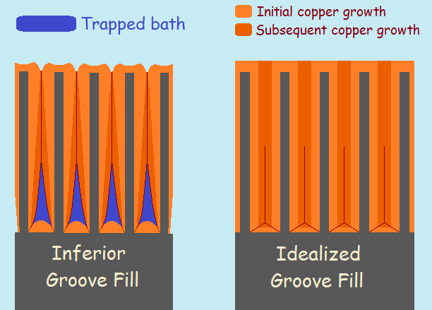
Normally, a little entrapped bath doesn’t hurt too much. But if a horn is heated to excess, grooves can burst, leaking entrapped bath to the surface. This problem is minimal if the grooves are not deep ones. The current density then more closely matches that of the surface and may fall in the current density range the bath “favors”.
There are special means allowing deeper grooves, but these involve considerable trial and error, not to mention patience. For instance, after a little electroforming, a low temperature solder or a conductive epoxy may be used to fill up the remainder of the groove. Then an adhesion coat of copper cyanide is applied⁵ and re-immersion into the electroforming bath finishes the job.
It is important to note that the transition from the nipple to the body of the mandrel may not be smooth, but involve a considerable step. If so, it may be necessary to apply some solder to that as well, since it may at least have grown somewhat weak, even if a cleavage plane is not noticeable. Otherwise, during machining, the copper on the nipple may separate from the copper of the body.
Voilà! Ready for Processing!
The electroform is completely grown. It is pulled out of the bath, rinsed, dried, and submitted to the machine shop. They machine the horn to be to its finished specifications and it is returned to the chemist or technician. What follows?
After a quick scrub, the horn still containing some of the mandrel the machinists could not remove mechanically, is cleaned in a sulfamic acid/acetic acid cleaner solution to remove any copper oxide on the surface. After a thorough rinse in water, the electroform is gold plated, often 200 to 500 microinches.
Another rinse and the plated electroform is placed in a 10% sodium hydroxide solution to dissolve the rest of the aluminum. Care must be taken to make sure hydrogen bubbles have not prevented some of the aluminum from being removed. Occasionally, hydrochloric acid may be used, either to accomplish the complete task, or to finish it.
The final steps are a dilute nitric acid dip to remove the copper flash applied to the zinc layer, which includes both the cyanide copper and sulfate copper applied before any gold was applied. Finally, if necessary, another gold plating is made. Then, the finished piece is given to the (hopefully) smiling electrical engineer for testing and further development.
Aside 1: The author was chemist at the National Radio Astronomy Observatory for 23 years – time spent almost exclusively on electroplating and electroforming microwave electronic devices. The procedures and insights expressed are those he himself employed.
Aside 2: Increasing the ratio of sulfuric acid to copper sulfate increases “throwing power”. That means, it improves the deposit of metal deeper down inside the grooves. However, adjusting that produces a rougher plate, not well-suited to electroforming. Adding considerably extra brightener (as permitted by Hull Cell testing) helps smooth the plate.
Note: You might also enjoy Random Electroform Art – How It Can Be Created
References:
- NRAO: Welcome to the NRAO Electroplating and Electroforming Work Page
- Univertical: Cu-Phos Phosporized Copper Anodes
- Finishing: Preparing acid copper brightener
- Finishing: Phosphorized vs. OFHC Copper Anodes for copper plating
- Products Finishing: Products Finishing: The Zincate Process
- QuirkyScience: How I Became the NRAO Electroplater / Electroformer
← Back to Math Logic and Design
← Home
Vince,
Not sure if you still read the thoughts on the articles, but currently I am training at the NRAO as a plater under the person you trained. I was googling electroforming, thought it was so strange I found the exact process we use and realized who you were! It’s amazing how you basically created the processes used at the NRAO and I am learning so much reading these articles. The site is also pretty awesome! Might stay here just reading for a while.
What a heart-warming reply. Thanks so much for it, Dee.