

Electroplating is the depositing of a metallic film onto a substrate, whatever form that substrate takes. One most unusual substrate is baby shoes! The electroplating industry contributes both functionally and aesthetically to a host of consumer products. Plating is both a science and an art. Electroplating bath chemistry is crucial. It is dynamic, ever changing. Frequent adjustments, tweaks, keep it in top operating condition.
Plating Bath Components
Every plating bath is different, but there are some components that are pretty standard for the majority of them.
1. Water
2. Metallic salt
3. An acid or an alkali version of the same salt as the metal
4. Brighteners
5. Anodes
Example
One example demonstrating the art-science dichotomy is the cyanide-copper flash bath, primarily used in preparing an object for the primary metal electroplating coat to follow.
This bath contains cuprous cyanide plus sodium or potassium cyanide (so-called free cyanide), although it has no brighteners. The anode is often noble-metal coated titanium or similar mesh. For this reason, as copper is plated, no new copper replaces that loss. Otherwise, copper levels may increase, damaging the bath.
Hull Cell
Testing an acid zinc chloride bath using a polished steel plate.
From experience, I learned that use of a small oxygen-free high-conductivity (OFHC) copper anode along with the mesh anode can assist in stabilizing copper concentration. Eventually, carbonate levels (due to oxidation of the cyanide) require bath maintenance.
Bath Performance Evaluation
The electroplater has a number of tools at his command to evaluate bath performance and adjustment needs. The Hull Cell is very helpful and simple to operate. We will discuss its use to test a bright, acid-copper electroplating / electroforming bath.
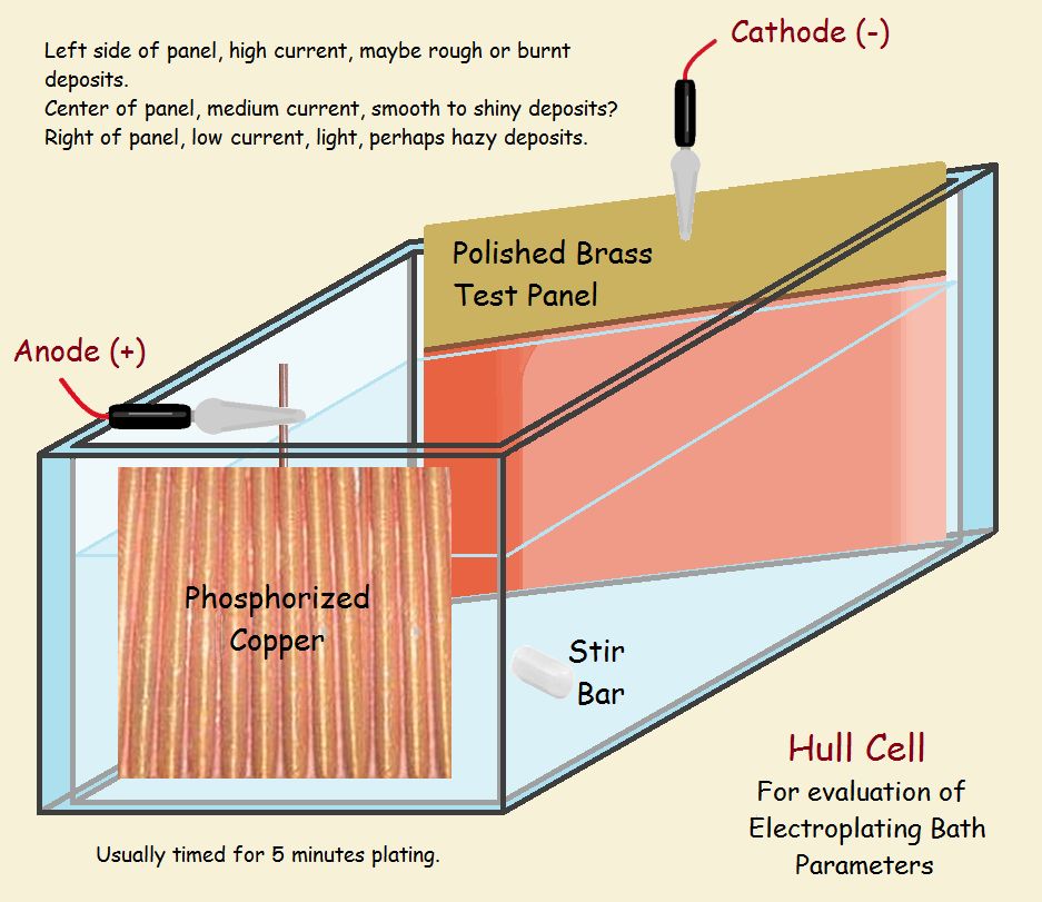
The common Hull Cell requires 267 milliliters of bath. Sufficient testing usually requires 5 minutes plating time. We forego a complete discussion of the apparatus, since we have provided a schematic of one and a video. We do not discuss specific operation parameters, which are determined by the particular bath under consideration.
Although large-scale operations may require daily Hull Cell tests, it may be used less frequently to diagnose problems as they occur. We will discuss some of the results I obtained during years of operation. First, enjoy the following Hull Cell operation video.
Typical Acid-Sulfate Bath Hull Cell Panel Results
The schematic shows the cell has two sides that are parallel, and two that are not parallel. The side that slants off has a blank plate installed to receive the plate, while the other side supports the anode. The plate’s closest side receives more current than the side that is further away. In effect, it receives the plate at the end experiences a higher current density. It is easy for the deposit to be “burned” (note the darker color in the drawing).
On the other side, the current density is generally lower than what is recommended for bath operation (note the light coat in the drawing). Quality plate is laid between the two extremes. How wide the usable coat in between is tells the technician if he needs to adjust the bath. It also shows what the problem might be, whether with the low current or the high current end. The commercial bright acid-copper bath we used had two brighteners, one for low-current and the other for high-current density performance.
Other Acid-Sulfate Bath Hull Cell Panel Results
On rare occasion, other problems might arise. One of these was tiny spots where plating did not take on the cell panel. This proved to be caused by tiny particles from the anodes that effectively insulated their point of attachment, effectively preventing plate from depositing.
Another problem was a swirling pattern on the plate. The panel was shiny and there were no pits, so this difficulty did not suggest the bath was completely dysfunctional, but it suggested the bath needed carbon filtration, followed by introducing fresh brighteners. After doing that, a repeat Hull Cell performance indicated normal bath behavior.
Finally, there was the rare occurrence of plating at the upper and middle ranges of the cell panel, but little to no plate at the lower range. This problem can be more serious if initial low current-density plating is indicated. It is good to check for anode to cathode current density ratio. Yes, the cathode (the piece receiving plating) and the anode (the negatively charged electrode) function best when the ratio of their current densities falls within a given range as well. For bright copper, a ratio of between 1:1 and 2:1, anode: cathode provides the best performance.
In Conclusion
The information provided here must surely suggest to the reader the practical wisdom of buying a Hull Cell test kit to assure a “healthy” properly maintained electroplating bath as a first line of defense.
Note: You might also enjoy Prussian Blue – The Traditional Blue of Blueprints: Its Chemistry?
References:
- PF Products Finishing: Choosing and Troubleshooting Copper Electroplating Processes
- National Radio Astronomy Observatory: NRAO Chemical Lab Report No. 12 (Vincent Summers)
← Back to Classic Science
← Home
Electroplating items like baby bootees or other memory keepsakes, is so common today, we forget just how much work goes into getting the thing to work.